...What I've been doing (and bear in mind I've only started a couple of months ago with blender) is the following:
1st: I get 3 views of the subject if possible (top, left, front), and opposing 3 as well if necessary (bottom, right, rear)
2nd: I insert them into blender's orthogonal non-persp views as backgrounds with a certain amount of transparency. I scale these bg images with respect to the 1 inch scale or starting reference solid.
3rd: Add the solid that best fits the part to be modeled. I've realized that in many cases modeling the whole thing at once makes it harder to unfold a reasonable part*. I'll try to use the simplest starting point possible, so if it's basically a box, I start with a cube. A symmetrical hull is really just a distorted cylinder.
It's at this point that someone said, that sound's great...hope to see some stuff. Well, it can still take a while to put something together. Even though I'm still too much of a newbie with Blender to write a true tutorial, I thought even a general overview of the process I used for one model would be helpful. Blender is not an easy tool (all 3D modeling tools are somewhat tricky). What makes most 3D modeling software difficult is that one can only use 2 dimensional I/O (mouse and screen) to create 3 dimensional objects. Blender can also be particularly difficult as the developers have consciously moved away from a traditional "Windows" GUI style to one geared around views and functionalities based on context. Blender relies more on the keyboard and buttons rather than dialog boxes or tabbed properties. X11 users should have an easier time with it. The version in this blog posting is Blender 2.54 beta.4th: Edit the solid along world axis lines as opposed to freely over 3d space and matching the tape to the background view. This last bit is tricky for hulls as I don't have accurate hull section plans for SF subjects (or any subjects really) so to some extent what I've done for the curvier subject is simply start at the front and work my way back trying to maintain the continuity of the edges.
I have been really interested in rounding out the early rocketry models from Neil's paper modeling site. Besides his "Bumper" kit, I repainted one as US V2#3 and another as #59. I also thought, having some US V2s, I should also have some Soviet V2s - namely an R1 (Scunner) and R2 (Sibling) missiles. These subjects are particularly interesting since, unlike the US, their V2 variants were operational and in production for military and research uses.
←The profile on the right is from page 149 of "Rockets and People" by Boris Chertok (vol 2) which is available from NASA's online document servers
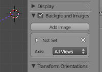
So item one, I need a 3 view. Well for this example let's concentrate on the R2 because quite frankly R1 is just a V2. Now a nice thing about rockets is that they are basically symmetrical radially so all I really needed was a side view. This was a tad tricky since it's not like the Russians made a lot of this information public, but I did find various images on the web. So starting with a profile, I inserted it into Blender using the background image insertion feature (right side 3D view panel). The resulting image was then offset and centered to where it would be easy to work with. In this case centered on the R2. It was ok to make it visible in all orthogonal views even though the XY plane was wrong, but for this shape top and bottom views were irrelevant.
At this point I added a solid to sculpt the shape from. For any classical rocket shape, the cylinder is perhaps the best starting point (from the "Add" option on the "info" panel). The cylinder was moved (grab function - "g") and centered over the view (either ZX or ZY plane) and in this case the top of the cylinder was selected and pulled upwards (first selected top edge + selected edge loop + top face center vertex, then grabbed along z only: "g, z"). I then selected the central point on the top face and pulled it up along the z axis to create the nose tip (below right). I then selected the ring of vertical edges and subdivided them several times (below center left)
| stretch cyl. and nose | section cyl. | scale to fit | Done |
|---|
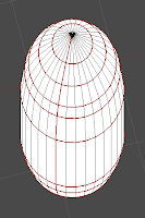
 The last step is to mark the seams for the paper model plug-in. While the paper model plug-in will create the seams for you, it will follow your marks preferentially (at least the last time I checked the FAQs). In order to prevent some version of THE Flying Spaghetti Monster, I marked what I thought were the logical seams. Each ring from top to bottom and one vertical edge from tip to base. On the following image of the model you can see the marked edges as red (this is a slightly angled view from top to bottom). Now blender can attach a texture to the skin of your model, but I haven't mastered that yet so the reader will have to follow that up for themselves. Instead I'll go straight to exporting the model. This is done from the "file" option under the "info" context menu.
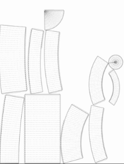
When you export a paper model, besides the project name (you may get several individual files using the model name as a base prefix), you can define the printout scale and the size of tabs. I shy away from most tabs so I won't focus on this too much. The printout scale can be a problem. The script will not automatically scale to fit the largest part onto a sheet of paper. You do get some information about how big the part/page mismatch is so it is possible to quickly narrow down to a workable scale factor. The more important thing here is to pick a relatively high image density for your output. If you stick to anything below 100dpi you will see jaggies and if you want to work on the image afterward you will be limited. Instead go for something around 200dpi at least. As a rule of thumb, for those who want to size their images conservatively, dpi should be at least half what you want to print it at. I like printing at 300 on inkjets and 600 on laser so files of around 200 work pretty well for me. Once you finish the export you should get an svg file (scalable vector graphic) with the parts in their raw form (if you can texture them, you would basically have a finished model now).

Thumbnail of R2 parts as generated
The script is nice in that it will automatically generate multiple pages if you need them, the limiting factor being only the size of the largest part itself. This points to the importance of marking seams. I could conceivably make this rocket shape with only one centipede like part. If I did that though I would have to make it rather small to fit onto a page. By purposely marking smaller sections, packing parts to a page should be easier and done to a larger scale. This is important as "jaggies" are less of an issue at the large scales on curves and diagonals.
Now the script isn't perfect. Part placement is curious and in many ways not ideal. The packing algorithm tends to push parts to the edges so losing an 1/8 of an inch on a part corner is not unusual. It is also not unusual for parts to be cut haphazardly if you don't mark seams beforehand. This is part of the reason I like the idea of finishing off the parts separately. I have also noticed that fairly frequently the parts are very distorted. I don't know exactly why, but I suspect it has to do with shape complexity and non-coplanar surfaces. A 3 point plane is always co-planar, but a 4 point plane can hide a saddle surface so that this shape is not directly unfoldable without introducing some seams somewhere. This version of the script will warn of such faces, but in general I have found that the best trick is to keep your unfold objects simple and only have triangular faces around what will be problem areas.
I'm currently positioning, painting, and fine-tuning the parts for this "Sibling" and I am planning a future post with finishing details on the R2. In future I am also planning to post a similar Blender work through for something with a trickier shape (Cargo version of Aries 1b? hmmm).


1 comment:
My dad made some stuff out of paper using Sketchup and Pepakura and published it here.
http://makeprojects.com/Project/Paper-Items-with-SketchUp-and-Pepakura/770/1
I like your site.
joshie
Post a Comment