Odds and Ends from my brain and interests. Given that it is meant to be much like my old cartoon strip at the Lowell Connector, I suppose it is eponymous (I also like that it does make an oxymoron of sorts)

If there is to be anything here of any regularity it should be about sci-fi, computers, technology, and scale modeling with origami thrown in on the side (at least not infrequently). Oh, I would also expect some cartooning too
Showing posts with label Modeling. Show all posts

Monday, January 13, 2025

2025 Arisia Paper Modeling Workshop

2025 Arisia Paper Modeling Workshop

The Trek Shuttle Returns

Well, after a long (long) hiatus, the opportunity to do a paper modeling workshop that is not just for kids has returned for this Arisia. Unfortunately, the panel length is going to be tight and getting a simple model that would be buildable in the allotted time is tricky. Various designs were tried out, which will make for good subsequent posts. The trick is finding something more interesting than a cube (say Borg starship) and yet still not super complicated. In the end I settled for looking at one of the oldest models out on the internet for inspiration. This led me to a kit published by the late Ulrich Prahn back in the 90s. The files are still available from a site maintained by Oliver Götz .

The Type 15 Shuttle - El-Baz


The Type 15 shuttle which was introduced in Star Trek - The Next Generation was meant to be a small 1 to 2 person shuttlecraft. It allowed individual crew members to do simple trips beyond the range of the ship's transporters. In a way it was really just a "pod" with interplanetary capacity. This is of course familiar to anyone who is a fan.

The featured shuttles carried various names and allowed the show to memorialize other participants in the advancement of science beyond Galileo and Columbus (even fictional ones perhaps in naming one "Pike"). Shuttle 5 - El-Baz is a reference to Farouk El-Baz, a NASA geologist who worked on lunar geology and moon landing site selection during the Apollo program. 

The Type 15 shuttle was designed to exist as a full sized prop for the show. As a result the design is fairly simple. More than just a box, its angled wall design and low engine mountings recall a sort of miniature version of the original series shuttle craft Galileo. The flat sides also work well for cardstock much like the original did for wood panels.

The Workshop Kit

While I originally wanted to scratch something up, it is easier just to work with Ulrich Prahn's kit, but some modifications were made to make it a faster build. The kit was scaled up as much as possible, while still limiting it to a two page kit. Some parts were also modified to allow for easier assembly. The most extensive change was coloring it in. Presumably, the kit was originally worked up before color printing was easily available so the original is only available as a black and white print (actually the originals were themselves ported to "gif" formats from postscript). 

The kit was also originally developed before the myriad of show references could easily be found. As a result it isn't exactly accurate to the miniatures used on the show. Then again, the show's full sized prop could vary quite a bit. The separate engines were never physically attached to the prop just dropped next to the fuselage more or less in the same area.

For a limited time, I'm going to have the workshop files linked here. I hope to work up my own version soon based on drawings from the original prop and photos of the shooting miniature. I have also added some detail parts that can enhance the look of this model. These details are left as an add on, since there really isn't enough time to work on it at the workshop. Given that you may want to try a more careful and less frantic build, the files are available below for download.

  • The Kit
  • Extra Details (if added, skip step 1 on the instruction sheet and do that at the end since these extra parts really pertain to those detail parts. You will need a hobby knife for these)
  • Instructions

General Instructions

Pretty much the standard for cardstock models. I've detailed stuff on the original workshop post back from 2011. With regard to the detailed parts, these were designed to fit this modified workshop kit and not the original. These parts pages are only temporary, and new parts pages will be uploaded when available.

Last Words...

If participation in the workshop has sparked your interest - GREAT. Paper modeling is a great way to approach the fandom without much more investment than resources you may have already, namely glue, scissors, and a color printer. Of course, there are lot of technicalities like the kind of paper and cardstock you deal with, specialty tools like hobby knives or tweezers, and special techniques in construction and assembly. For that I would suggest you visit my subject page off this blog which has links to other article pages on paper modeling and try out Ulrich Prahn's other kits linked here and above. While the El-Baz is the simplest, the others are also not bad beginner kits. Moreover, you can practice kit modification since if you want them in color you will need to modify them with some photo/drawing software such as Gimp, Krita, or Photoshop which is fun in an of itself.

Monday, January 25, 2016

Mod Mon: Paper Dragons and Workshops

Workshop Models: Paper Dragon - a simple paper models for beginners

Umpteen apologies. This link should have been put up ages ago, but I kept putting it off. This is the posting for the dragon paper model I created for a Fast Track workshop at Arisia 2014. The original purpose was for a fast paper model that kids could build. It needed to be easy to put together, require minimal instruction, and at the same time would look somewhat interesting. I had a chance to do this again for 2016, so here's the update. Since then, I did another workshop and another model which I will be adding soon (a familiar telephone box).
     The initial section is some ideas and experiences of doing card modeling workshops. If you just want that dragon, then skip down a bit.

A word about Workshops - Read if planning for one

     The thing about workshop models is that typically you have very little time to work on them, generally not much more than an hour. Age is also an issue when designing or picking out a kit for it. You should consider the subject matter. While some of the simpler things to do are basically boxes or cones, it pays to make it somewhat interesting to your intended audience. Young children don't always sit still for long periods of direction and instruction, particularly if the rest of the room is running around doing something else. Even when working with adults, consider that the time for direction and instruction will take away from the actual build time. As a result use a kit with few parts that glue together easily. You can take advantage of subjects where the location of parts are more self explanatory, such as cars for example - where the wheels go is fairly obvious (see discussion about Knowledge in the World and Knowledge in the Head from Don Norman's Design of Everyday Things).
     While there are many things that are just a box, even a box can be made a little more interesting with a little detail skinning, like a Borg cube.It is possible to do interesting things with cubes as well. if you stretch a cube out into a rhomboid and it can be a racer or a rocket, and still be not much harder to build. Some Minecraft and Hako subjects can fit that bill nicely.
     One thing to also consider are the costs of running it. While it is nice when the people running the workshop can print the kits for you, ideally on a color laser printer, the cost of color print outs can add up. Picking a kit that uses only a few pages, say just 1 or 2, can make that more manageable (truth be told, I can barely manage a dozen builds at a time, so 16-20 kits is pretty much my max for print outs). Another strategy is picking out kits that are basically monochromatic. Here you can take advantage of using a standard black and white laser printer or even a photocopier to create the kits and simple use colored card stock instead of that valuable ink. Sci-fi subjects might have an edge here given the number of subjects that are mostly white with just a dash of color here and there.

The Dragon - a beginner model

     The dragon is a design idea that allows participants to color in and finish it in whatever fashion they saw fit. Given that the original workshop was for Arisia's Fast Track, which is for ages 6-12, I also wanted to keep it fun and light, but more intricate than a Borg cube. The model has very few parts, goes together easily, and be very forgiving of poor folds and missed attachment points. There are also certain obvious locations for the parts, i.e. head goes in front, tail in back, feet over the leg stumps. The only drawback is the zig-zag of the tab/scales can take a while to cut, but it doesn't have to be perfectly cut either.. It's also cheap, being just a black line drawing; ready made for photocopiers or black and white laser printers.
     The design doesn't use internal tabs, but instead uses the outward spines as external tabs to attach several parts. These are matched up and glued together. You shouldn't need an X-acto or any such implement to cut this up - safety scissors should do just fine. Tabs are fairly broad and cut at obvious angles so while scoring folds would help, it isn't necessary. The parts should naturally fold along crease lines.
     I encourage builders to color it in any color you want and it will be easier to color in before assembly. Felt tip pens are better as you are less likely to accidentally draw over glue points, but the way the glue points are designed (external tabs), you should be ok even with crayons (the wax in crayons would normally make gluing pieces together difficult). Another design idea is gluing things onto the finished version, such as from colored paper scraps or construction paper. The wings themselves are only printed on one side, so you will definitely have to finish them off on the reverse side. While ideally you do want to use card stock, which is available in various colors from office supply stores or craft shops. I have printed this model on construction paper (you will probably need to cut it down to 8.5"x11" to fit into your printer) and it does work, but construction paper is flimsier though and dragons made of this are more likely to suffer from wobbly legs and flimsy wings. In this case, some strategic reinforcement from scraps might solve that problem.
  The model(pdf)    the model (png)    the instructions 
Dragon.pdfDragon.pngDragonIns.png

Basic Dragon Instructions (text)

You will need some scissors and glue. The parts represent 2 mirrored halves of the dragon, the left half and right half. Let's start with the head+body first:.
  • The body consists of 5 parts: The left, the right, the head spacer, the stomach spacer, and the tail spacer. Instead of tabs that glue on the inside, the "spines" are the glue tabs. After cutting those parts out, fold the spines out slightly
    1. Glue the two halves together. Bend the spines back a tad, and put a drop of glue on each of the top spines. Then match the spines from each half and press them together to glue. Allow it to dry. Suggestion, don't do all at once, start at middle, then do the ends.
    2. Open up the body in the middle and glue the stomach spacer by gluing the spines together like you did before. You will need to fold those spines outward a bit to make that easier. I have found it works easier if you only do one side at a time, put glue on the dragons spines on one side, attach the spacer, allow to dry a bit and then do the other side. Once dry (2b), pinch the nose and open it up a bit by squaring off the "upper lip" (unless you like it pointy).
    3. Get the smaller head spacer, and glue these spines to matching spines under the head much like you did for the stomach (one side first, then the other). The head spacer also includes the lower jaw, so just glue the spines.
    4. The tail spacer and fins attach like the head spacer. Simply match the tail fins to the underside fins on the tail of the body
    5. The front legs carry the wings. Glue the center of the roundish shoulder of the front leg, and on the leg stump on the body, but not the base of the wing. You might want to fold the wings outward slightly at this point to glue the wings pinned back.
    6. Attach the back legs by gluing the hip area of the leg over rear stump on the body. Once dry you can spread the feet and legs as necessary to get a proper stance for it
  • To some extent, the positions of some items can be shifted slightly. Perhaps more importantly, feel free to modify some parts to better suit you. If you want different wings (say butterfly wings), feel free to cut them off and draw up your own. Another idea is to paste stuff on it like bits of paper to make scales or build out the wings and tails with strips of colored paper, whatever.
The jpeg version can be modified with simple photo imaging software. The original design was limited by keeping it to a single sheet of paper. Whatever you can imagine would be fine.

Gallery of Dragons - Papercraft workshop Arisia 2016:


Arisia Fast Track 2016 Bonus

I had a spare set of kits for an experimental one I was ironing out at the time. This character, a certain Encoded Bill is a fairly simple build, and still kind of beta, but if you are willing to try it out, the kit and instructions are here. I'll go into more detail for the next workshop blog entry. The only thing to say here is that I did make it with a "following eye" feature which you can try out. It involves cutting out the drawn eye, and placing the pupil piece provided against the inside back wall behind the hole. It's otherwise a fairly straightforward triangular box, arms and legs fold over for strength and to create feet arms. A simple forehand and flame part allows you to finish off the hands nicely. Good luck trying it out.

In Black and White (color it in) or in Color and the instructions (Links included as soon as I perfect the "following eye feature).

Sunday, November 08, 2015

Arisia 2015: Miniatures and Modeling for Gamers and Fans

Various recent releases (clockwise)
Monarch Models "Ghost",
Revell Star Wars 7 Tie, Pegasus Luna,
Moebius Colonial One, Airfix Angel
Interceptor, Revell Ger. Enterprise,
Bandai Gundam, Dragon Tranquility
Base, Moebius Ranger and Flying Sub
McFarlane Walking Dead, Pegasus
Nautilus, Fantastic Plastic Avatar
Shuttle, Moebius Johny Quest
Dragonfly
 
In spite of being in one of the most hidden rooms in the hotel, and placed right up against Masquerade (which is single most attended item this weekend), we actually had a fair amount of people there. Most of the audience were familiar with one or another aspect of the topic, but there were a few self acknowledged newbies in the group which was nice. My fellow panelist were T. Christopher Davis who specialized in gaming miniatures and terrains, and John "Madman Lighting" Cook who is an award winning scale modeler as well as a manufacturer of lighting kits for models. I brought along several of my old models and a couple of new paper ones, and not surprisingly for me, got to talk about the paper end of the hobby.
     Arisia has a large gaming component among its attendees. The
gaming track at Arisia consists of various active game rooms, discussions about games, video games, and LARPS. It is definitely a con that doesn't forget that science fiction and fantasy is just fun. Part of this is also reflected by the amount of the con
Dwarf gaming miniature
from Basicks kit
devoted to costuming, both as a topic of discussion and visibly displayed by participants in costume reflecting their fen interests (be it creative anachronism, cosplay, subject fandom, or just whatever comes to mind).  It was nice that this year we got at least one panel devoted to those of us who like to craft our fandom in miniature instead of wearing it.
     The thing about this hobby is that it is currently in a kind of golden age. Never before have so many different subjects and areas in this genre been available for builds. The greater number of genre films and TV shows, comic books, and games is part of the reason. Another reason for the growth of this niche in the hobby is the increasing number of fans who really embrace their "geek"ness. So you prefer working with miniature starships and dwarves, so what, they are cool.

What was it exactly?

Basically, science fiction and fantasy in miniature for a variety of purposes. There is of course the replica of the science fiction vehicles we are all familiar from film and television. I personally believe this also covers the replication of props, sometimes to a higher fidelity than those that were actually used on film (admittedly this can crossover into costuming). There is also the creation of elaborate stages in miniature and game pieces for use in table top gaming. It is a creative aspect of fandom that also extends into other media such as Lego construction and 3D virtual models and 3D printing. Another expression of the hobby is in figure modeling, either full figures or busts (aside from game pieces). These figure models tend to have a wider span covering not just science fiction, but also horror, fantasy, and even popular culture and humor.
     Given the collective experience of the panelists, we initially spoke on the nature of our hobby from our individual point of view, how we work, what we found interesting, what it seems to be like (something which I think this internet cartoon captured quite well.

We focused on discussing the techniques and tools involved in how to put our stuff together. We mostly opted for opening the floor to questions to get a sense of what attendees wanted to know.
Lindberg models released in 1954 what is perhaps the first science fiction model, although given the saucer craze at the time, they may have thought it was an educated guess at a real artifact. It has been re-released several times since.

How does one get started?


A fairly basic question which we got early on. Well I guess the starting point should be your nearest hobby shop, or perhaps (given that these have become fewer and farther between than they used to be) a nearby crafting chain. The latter choice is problematic in that your choices, particularly in the SF/F area will be limited. Some stores specialize in gaming resources and carry miniatures. Comic book stores may also stock both gaming miniatures and SF/F models as well as limited supplies for working on them. Occasionally major franchises, like Star Wars, will license miniatures, but toy stores nowadays only rarely carry models (although some starship modelers are currently thinking about how to work with the new giant Hasbro Millennium Falcon and X-wing toys. Reworking actual toys into quality models is not unheard of, but it is a bit of work). Of course there is always the internet where you can either find many items on amazon.com or other more specialized sites (I'll put the link list at the end).
Pre-painted
Revell SnapTite
mini-kit
     The range of models and miniatures can also vary. One can start with the finished collectible or nearly ready finished variety. Many models currently are designed as simpler "snap-fit" kits that don't require glue, and are frequently already painted. A whole series of small scale Star Wars figures are marketed this way with very few pre-painted parts in bubble packaging. This is ideal for children or people who have never built any of these types of models before. On the other hand, more experienced modelers prefer the traditional paint and glue type. This is because all kits often reflect a compromise of one kind or another between price, ease of construction, size and so forth. Pre-painted kits may not be the "right color" and since you can't "test fit" a part, or sand seams (it ruins the finish) it can create problems. This all depends on questions of accuracy* and detailed finish.
Madman's EarthForce Starfury from Babylon 5
Madman's EarthForce (B5) Starfury
with his lighting kit (on display
during this session)
    While in general, it is not a particularly expensive hobby, one can expect to spend a certain amount in setting up a basic workshop (see tools next section). Some kits can indeed get expensive, particularly if one starts adding aftermarket parts such as detail sets and limited run "garage" kits. If you have your heart set on something that is out of production or only available in Japan, well that is an order of magnitude more. Of late the ultimate kits are huge, limited run, 3D printed ones such as the 1/700 scale Cygnus from "The Black Hole" which was available from Shapeways (in sections, runs up in the thousands).
     Take for example the Moebius updated re-release of the old Orion III model from Aurora. The basic kit is actually not a bad starter kit. It is reasonably sized, has relatively few parts, and no particular assembly problems. It typically retails for $30. Unfortunately, the classic Pan Am markings are still under trade mark, so it doesn't come with any. Fortunately you can get aftermarket decals from a couple of decal manufacturers. Prices range from $7 to $17 (the latter include alternate versions, such as NASA or USAF). DIY inkjet decal sets to make your own run around the same price, although you should get enough material to do several models. If you want to get really fancy, you can add interior and exterior detail with a brass photo-etch set at $27. So you could make this model amazing for about $60-70 (paints, brushes, cement, and fillers are overhead).
     One aspect not to be overlooked is scratch building with whatever you can find. Many amazing subjects are created from found items and interesting packaging such as Easter candy eggs, empty pill canisters, and wood. It is also important to know that from a commercial point of view, some things are unlikely to receive a wide release, and garage kit version releases that may happen can also be very expensive. A little creativity can go a long way (see this "pickled alien" display for instance)

*Accuracy - a side note:

     The thing about accuracy is that these are fantasy objects (real space excepted). Accuracy is thus a relative thing. Often the subject may only have existed as a variety of shooting models which don't entirely agree with each other. The true color is an endless question, particularly since that depends on a variety of unknown aspects of the model's photography: lighting, exposure, color balance, monitor and can be very subjective. Even scale can be open to question. It is well known that most SF ships on film are generally smaller on the outside than what is portrayed as the insides.


Tools of the hobby

The topic most asked about in one way or another regarded tools and their usage. The question is often one of finish and how much you want to spend in blood and treasure. Typical tools depend on your media: plastic, resin, paper, clay, Legos or old pill and film canisters. Paints are also necessary and can vary with different surfaces. Paint can be applied with brushes, air brushes or even specialized markers. Additional after-market parts or decals, or even kits for adding lights or extra details such as photo-etched brass (PE sets) for commercial releases are also available.
      Chris Davis and myself admit that on a very basic level, we don't want to spend too much money on this, so we may rely on substitutes. An interesting comment Chris made is that often the railroad hobbyist have developed specialized tools and materials that you can find at the hobby shop at a premium price, but cheaper equivalent may be available at your local hardware store.
     A classic example of going for the cheap solution is the usage of pink insulation foam to build up terrain for a game field or a diorama. The material is relatively cheap in bulk (one sheet should last a long time), and can be carved with typical carving tools such as small files and hobby knives and easy to paint (just not spray enamels which will melt it, although I've seen that done for effect). The only specialized tool it needs is a hot wire cutter to make smooth cuts (it melts through the foam without tearing it).
      John Cook recommends a good airbrush to really improve the finish, both in overall coating as well as detail paint finishes on a model. To demonstrate he brought in his Klingon BOP as well as a Babylon 5 Starfury. Both kits were meticulously painted and carefully shaded as well as equipped with lighting kits which he sells as aftermarket add-ons. Many find lighting a key component to many a starship miniature (You can see a detailed article on his Starfury at the Starship modeler site in the "Wrecks" gallery).
      I myself added that in the case of paper models, you don't need much more than glue, scissors and a good printer to get started (or printed kit as some are now available in your local bookstore). That being said, sticky glues are better than white glues, sharp blades with a steel edged ruler can sometimes be handier than scissors, and a variety of paper weights will help, not just cardstock. I have more details in a previous posting.
      You can find better detailed listings on hobby web sits, but this is a brief overview of things we said:
  • An X-acto knife or its equivalent (yes! the knife of Exact-Zero!)
    • It is handy for all 3 types of modeling: plastic, gaming, and paper. Note, blades can come in several types, not just the classic no. 11 (with regards to kids, these are also very sharp)
  • Jewelers files
    • These often come in sets to provide a variety of sanding possibilities and even limited drilling into surfaces and punching into soft surfaces. 
  • A pin vise (a favorite of Chris for gaming miniatures)
    • Basically a small hand drill. Allows you to drive small holes into an item accurately with good control. Handy for adding steel pins to help hold parts together.
  • Cyanoacrylate glue (aka Super Glue or Krazy Glue Brand - The KraGle)
    • While plastic models can be made with just plastic cement (check to see that it works with polystyrene), Cyanoacrylate can make particularly strong bonds and works with a wider range of materials and mixed materials (e.g. brass to plastic). Accelerators make the bond instantaneous, but can burn due to the chemical reaction (and since it is glue, if it's burning you, it's also stuck on you). Some people also use it in paper modeling as it will soak into paper and make it hard and plastic like (I personally use nail polish for that effect).
  • A vent hood
    • If nasty chemicals and fumes are involved you may consider this. Spray paints and some of the nastier solvents (such as acetone) can be problematic indoors. The internet can provide many DIY designs. There is some science to this, so check out user results. If on the other hand you stick to brushes and fewer volatiles, you should be ok without one (just watch for spills).
  • Some miscellany: sanding paper, sanding blocks, and filler
    • We did mention the use specialized sanding tools that can bend around parts, but generally a means to sand from medium to extra fine is useful in trimming mold seams and joint seams. The use of a block is important, but you can make these yourself by using a bit of wood or foam when it has to conform to a shape. You can even use nail files and for finer grit, glue finer paper onto it. In plastic modeling you may also need this to sand down filled in spots. All this sanding is often in conjunction with plastic filler putty used to fill in gaps in seams or smooth out joins. Putty is available in most hobby shops, but curiously my local hobby shop guy pointed out you can get this cheaper from the auto supply shop as the small ding filler putty (not to be confused with the 2 part can of patch resin).
Oh, something we did forget which is both trivial and very important: If you buy a kit that was molded (plastic, resin, etc), wash it in dish washing detergent to get the mold release agent (grease) off of the parts before you start working on it. This will greatly improve the hold of glues and cements as well as paint and paint coverage.

Where to go and look

To end this posting I just want to set out some links to find more information about participating in this hobby.
The truth of the matter is that it is hard to give a complete picture of making miniatures and models from one panel session and one blog post (this one is already a tad large). Again it is a question of satisfaction with the finished product; you can pretty much make do with the appropriate glue/cement, a hobby knife, bottle paints and brushes (and even dispense with the latter if the subject is pre-painted). You can visit general modeling sites or books (almost every library has books on model railroading and a lot of the techniques discussed there apply here) for more advanced techniques such as weathering, oil washing, decal placement, painting, finishing clear coats, airbrushing techniques, dioramas, etc.
      Well, I hope this gets people interested in the hobby, or if they are modeling interested in this niche, I also hope that this is looked up by those that were interested, but didn't make it to the session because of Masquerade (hec, my daughter was in it and I missed it).

My cardstock Narcissus which was on display at the session(will be downloadable soon...promise)
     

Monday, April 08, 2013

Mod Mon: Creating Bulkheads from 3D model (II)

Part 2 of working with Blender to generate bulkheads

The last posting (Part 1) I wrote about creating a solid model from a 3 view that had relatively detailed outlines of loft lines on a ship's hull. Again, since the purpose of the example is to show how I did it, the model is not exactly what I would call particularly accurate. If I was to work on this for a finished version I would probably work it into a few subsections with a higher polygon count for each. Still, this should be good for now. As a reminder, this is done specifically with a somewhat deprecated version of Blender, but it should probably apply with quite a few different 3d modeling software packages. Also, this is done with an eye for a card model, but it should work fairly well with paper or plastic card scratch building.

So you got the shell of the thing

We prepared the hull in the previous posting, so how would one generate the bulkheads to provide the structure for the model. It's at this point that I would start making separate files. Why? Well, this part will be somewhat destructive. This may be particular to my software set up. I've been using Blender for some time, but I'm not a Blender guru (particularly since they keep changing detail bits, which is why I haven't upgraded yet). I'm using a paper model script that allows one to take a 3d model and cut it up and "unfold" until the pieces are flat, like flattening a box for recycling. The ability to generate this easily is limited by the complexity of the model.

If you read some previous postings I have made on using this script, you will read about some of the problems. Sometimes complicated internal corners, such as the ones created by bulkhead spaces, can create problems. This doesn't mean it happens all the time. Sometimes it works just fine with everything in one file of objects, but other times...well it's not so good. As a result I often have a structural file for bulkheads and such and a hull file. The important thing is that if you do this, the common points must match, otherwise trouble will ensue. I sometimes insure this by importing the hull file into a structural file as an external object so I can still see it. That is somewhat advanced and I won't go into it as it involves more complicated object relationships (Yes, true Blender people will gripe that this is a bit of a bearskins and stone approach, but it works for this purpose).

So, at this stage I'll save the hull, and then save the file as "hullStructure" to start working on the internals.

Carving out the Structure


The process is similar to what went before with the hull creation. Before we created a large rectangular block to carve our shape out. In this case we want to outline the interior shapes to the existing solid. First I'm going to start the outline of the top deck. This will follow the second line from the top. Since the model is symmetrical, I'm not going to worry about generating internal spaces for the whole ship, but rather just the port side. So for starters, I selected all the vertices along the port edge of the hull.

These I deleted to make the next steps clearer.


I followed this up by starting a longitudinal bulkhead along the centerline, starting at the front.

Taking the first cross section, I dropped a line from the center down by selecting the center point on the first section and then the one located directly below it (Blender "f" + 2 vertices creates a line segment).
This segment was subdivided, and the midpoint was adjusted as necessary to be co-linear with the deck height (Blender "g+z"). When done, selecting the three points at this level (Blender "f" + 3|4 vertices creates a face), the first top deck section was created.
The process was repeated dropping a line down from the next section, but this time it was subdivided, then subdivided on the segment below allowing a potential for a waterline section. These middle points were adjusted to the right heights. Faces were then created by selecting the co-planar points and doing a make face operation ("f").
At this point there are also enough points to start making the vertical structure. Selecting line segments it is possible to start building faces along the centerline (Blender can generally make a face with any 2 line segments as they have 4 vertices, or 3 if one is shared). These are shown highlighted on this image (Note that at this point extraneous line segments were deleted)
In a similar fashion, vertical bulkheads that shape out the hull can also be created
The rest of the centerline structure was created by dropping lines down, and then selecting each line segment to create a face (In Blender, as mentioned, any two lines, will create a face with 4 or 3 points). NOTE: If they are seriously not co-planar, Blender might balk, but the paper model unfolder will definitely not work.
You can see the end result from repeating the process of creating faces from the existing points once the center vertical faces and deck levels are set. On the right with the remains of the hull, and then on the left after the remaining hull is taken out. Since bulkheads should align with axial views (front/back, top/bottom, left, right), you can easily check by using those views to see the planes lines up (in Blender, keys 7, 1, 3, in ortho-graphic view [toggle 5 between ortho/perspective])
At this point the bulkheads are done. You could add seams and let the unfolder script make these parts, but you will probably end up with a lot of little pieces as the points were bulkheads intersect will be considered seams. On the other hand, you might get a better result if you explode the parts yourself. In theory, you don't need the unfolder script to do any real work since bulkheads are already flat. Here I selected the pertinent faces and then performed a "split" operation (In Blender "y" key) which "splits" common vertices creating a separate object. This I then moved away from the rest. I did this first for the vertical spine, then the two horizontal decks, which left just the cross-section bulkheads all by themselves.


And that's basically it. At this point you can use the paper model export function in Blender to have it crank out the shapes which should come out as one piece. You may need to put seams on the long pieces (a blender operation since it is also used for defining texture skins for the model) to force breaks since depending on the scale you finally export the file (a setting on the export paper model script) they would probably not fit on a single letter or A4 sheet.

Hope this posting helps with anyone trying to create structures for their models using 3d software.

Monday, April 01, 2013

Mod Mon: a Blender Hull for Bulkhead Generation

This posting is meant to be a detailed answer to a question posted on the StarshipModeler Forum on how to generate cross section bulkheads from plan drawings,  presumably orthogonal views with detail cross section lines. While the forum post was for plastic models, and this process is generally for paper, the process is transferable to plastic card scratch building.

To create an example I looked for a publicly available set of plans that show cross section lines. An adequate one was found for a prototypical design for an 19th century Arctic exploration vessel of the US Navy at www.history.navy.mil which was associated with the ill fated Jeanette Arctic Expedition, although it appears to not represent the Jeanette itself.

The software used was Blender 2.5x, which is admittedly old, but I'll try to  keep the description general so it would be applicable to any 3d modeling software.  The features that are used most often are:
  • insertion of primitive objects, 
  • selecting faces, lines, or vertices
  • creation of lines and faces from selected vertices or lines
  • scaling, both objects and selected vertices, particularly along a single axis (such as scale in X direction only)
  • Merging vertices and extrusion of vertices, lines and faces from existing ones, particularly along a single axis.
  • View frames set to either top/bottom, left/right, front/back

Step1: Get the Views in the right place:


I took the original sketch (and it is really just a sketch) and generated a good set of orthogonal views by correcting the slight tilt in the original and creating a reasonably clear front and stern elevation. This was done with "gimp"(GNU image manipulation program), but any image manipulation software, such as Photoshop, should be able to do this. The sketch had no top view, but that was ok as what we are really concerned here is the general hull shape from the top deck down. The file was saved as a png file. Again, the purpose of this exercise was to illustrate a process and not generate a real model, so this sketch is not super accurate. Of course on the other hand, I hardly ever work with views that have any sort of sectional lines at all, so this should be interesting.

     This version of Blender allows one to add various types of images to the blender files as a "background image" property. Most 3d viewing systems allow this in some manner, shape or form. In Blender these may be visible only in particular orthogonal views. I've seen image captures of other systems that allow you to set it at the origin so that it is also visible in multiple angle views. (aside: Blender allows visibility of one image in all orthogonal views, but this is only practical if the object is symmetrical in all axis, like a sphere, or perhaps if some of the views will not be  used such as the radial symmetry of a rocket body).
     Blender allows you to center and scale the image to your liking in the viewport. If you are going to use separate views (top/left/front), it is important to pick a particular point of the plan to be at the origin (0,0,0) to maintain consistency. An annoying aspect to this in Blender is that the background image is not optically at the same point so to speak, meaning that even though you use a set of images that are scaled equally, when in the viewport, the actual scale set may not match. This was the case in this project. Often you will not be able to get the plan scaled correctly until you have defined the parameters of the 3d model, so you many initially only work from one view, then check and size the views accordingly.
     In this case this happened to me. I initially set the origin at the bottom of frame 70 for left/right views - no problem. Then I set front and back, and it turned out ok for scale as well. I worked most of the process described next with just these views, but when I switched to "bottom" view, well the image was much too small, and to match the loft lines I had to scale it up a tad. Another annoying problem with Blender is that well, it's got it's axis screwed up in that it puts "front" in back and "back" in front (at least if I'm following a left hand rule), so I did have to remember to swap the views (It probably has to do with some drafting rule).

Step 2: Insert a primitive to sculpt

One can use any number of primitives to generate the basic shape of the hull, but the most logical thing is to use something that can easily approximate your target shape. In this case, a cylinder or a cube would probably be good. I picked a cube as it would allow me to start off  with few edges and vertices and add as needed. It is also closer to the traditional method of hull building from a block of balsa.

The cube was placed and scaled to the sketch on one of the views. I am starting from the starboard view. The cube then needed to be stretched to the appropriate length. This can be done by selecting the forward and back face and move it along the y axis (in Blender, select face, g, y) until you get it to the desired length. Note, I didn't take it all the way to the end, this was done just to avoid several merge points as the ends of hulls tend to be pointy.


Step 3: Shaping the object


The hull is bilaterally symetrical, so I set up a new edge that would split the object down the middle.
First I selected an edge that goes across the shape. Then I selected the "edge ring", namely the other "parallel" edges around the object. 
Aside: In Blender this is a possible selection operation once an edge is selected. The word parallel is quoted because in truth it isn't parallel lines being selected but co-lateral segments. If this where a sphere, it would select the segments along a particular cross-section. Once shapes become more complicated the actual path of the ring might be less clearly defined and no longer ring like

With the edges selected, I can carry out a subdivide operation on them. These will neatly add a vertex to the exact middle of each line segment effectively spliting the rectangular prism into two equal halves. Each half represents the starboard and port half respectively

Select one of the vertical edges on the faces and select the ring. Carrying out a subdivision will then result in an equatorial line.

Select this equatorial line and lift up or down to match one of your draft lines in the side views
The quick way is to select one segment then select the "loop" of segments which selects the collinear segments to that line. In Blender, once selected you can use the "g"+"z" keys to command move selected along z axis.
Repeating the process selecting the lateral ring will generate all the horizontal sections in the plan
Each cross section may have to be moved in a similar way, by first selecting the cross-section loop and moving solely along the y axis in this case.
The block should now be sectioned to match the sketch. A couple of things I didn't do was stretch to cover the prow or the fantail. I'll do these two bits differently.
At this point I'm ready to pull the block closer to the shape I want. Starting at the front, there's a couple of options. One would be to extrude the prow. The other shown below is simply start pulling out the front center line to match.
I selected the top center vertex at the front and pulled it out to match the sketch (g+y). This generated some distorted faces so I subsequently  subdivided some line segments and then cleaned up a bit by getting rid of edges (x in blender) then adding some new edges (f in blender).

I selected the next center point immediately below and pulled it out similarly. The special case here was selecting some edges to create a new cross section through subdivision, and then pulling the vertices to get everything to match.
An important feature of must 3D programs is the ability to get vertices to line up along an axis or slope. Since the alignmnets here were simple I simply made sure that the cartisian coordinates of co-axial points lined up. Also by setting up the centerline along the origin, mirrored points can be set up to be at the same but negative cartisian coordinates.


Repeating the process of pulling the center points I eventually approximate the forward edge of the prow
Shaping the sides now requires selecting a pair of mirrored vertices along a co-linear axis (this case x) to match the drawing for that cross section (Blender select points then "s" "x")Repeating the process for the rest of the points, I eventually arrive at the rough shape of the prow.

Moving down the cross section starts to create the shape.
These points set up an unique, but not unusual situation, that is that all three should be merged together. In Blender I select these three points. Then alt-m selects "merge" which in this case was the last selected, this being the center point of the three. (Note: I didn't repeat this for the other sections instead I placed the ends .1" off the center-line...see detail bottom view)

More or less this way the forward hull is generated. The limit is in that to shape the rear you need to see the rear elevation. Note that while doing this I alternated between solid view (shown here) and wireframe which allows you to see the background image. This will make working with the rear trickier since in wireframe view the front will be seen and particularly when in non-perspective view, which vertex you are looking at can be confusing. Switching between solid and wireframe to check your selection will be important.

The fan tail was done slightly differently than the bow, in that instead I extruded that deck from the back frame. This was done by choosing the face that makes up the point adjacent to the fan tail. The "extrude" operation was chosen (Blender e) specifically along the y axis (+'y' key, otherwise it may extrudes along a normal to face), and pulled to match sketch. Following this, mirrored points are manipulated in much the same way as before to shape the stern section
The fantail required some additional clean up as the faces were severely distorted and curved. I deleted some edges and reconnected some lines creating a new set of faces that follow the contour of the hull better.

The center frames needed to blend the stern with the bow, and it simply required matching the coordinates along the co-linear y axis points at the edges of the hull. This was done by selecting the affected points and matching the x coordinates (z having been set when they cross-section was lifted to match the right height already).


The end result is the more or less finished hull. Less so because many of these 4 sided faces are not flat, and as a result cannot be "flattened" into a shape transferable to a paper model or subsequent plastic card template, although it may be ok for 3d printing hardware. For cgi, well, there are just too few faces here, but trust me, you want to keep this number low for generating paper kits. Creating flat faces requires changing affected faces into triangles (quad to tri operation in Blender, ctrl+t). By definition, triangles are flat so they will not create a problem. I'm not going to detail that bit just yet since our main objective is creating bulkheads, but since this has been pretty time consuming, I'll leave that to a part II posting.

Coming next: Part 2, making bulkheads

Monday, December 03, 2012

Mod Mon: Current WIP and lessons learned so far


In preparation for Arisia 2013, I've started to look for a simple model that will fit in 2 pages and be built (or at least mostly built) in about an hour. As usual, foregoing the Borg cube because it's a little too quick, trying to find both interesting and easy is proving rather difficult. So currently I've been following several tracks simultaneously.

The candidates are:
    snapshot of possibilities
  • The Last Apollo, the CSM for Apollo-Soyuz
  • The Narcissus, in a greatly simplified format
  • The Dark Star, perhaps including bomb 20
  • The LIS space pod, pretty orange
  • C-57d, a simple saucer
  • General impression of a typical London police phone box from the 60s
For the winner, I'll have to get back to you later, but for now I figure I could pass on some insight into kit design and some Blender paper unfolding foibles I've run into so far.

Keep it simple


The object of using Blender is to make creating parts for the kits easier, not creating a 3D model of the object. Thus there are a couple of important things to keep in mind: first, I don't need the whole object, and second, the fewer the polygons, the better.

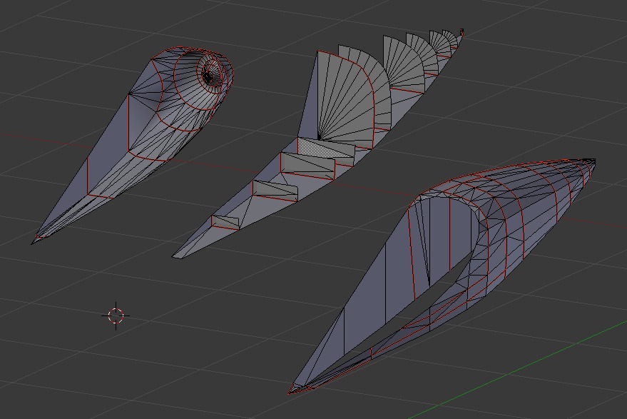
Port engine assembly for Nostromo model on Blender
Port Engine for Simple
Nostromo model. No starboard
engine drawn since it is identical.
Why don't I need the whole object? Often the subject express some sort of symmetry. Now for some subjects, the shape is simple enough that getting the whole shape done when modeling is OK. Take a missile fuselage for instance. It is relatively easy to create a pointed cylinder so, one just does it, but consider the Narcissus for instance, and more specifically the engine assembly. In the simple version I was working on, it was easy to get a lot of the shapes done based on cube primitives, but why build 2 engines; the left is just like the right. So you create one, print twice. A more subtle situation would be the rear stabilizer on the Buck Rogers cruiser where the left is the mirror of the right. This is easily rectified after the part is rendered, just copy and create a mirrored rotation. So for creating a bilaterally symmetrical subject, you really only need one half. Given the quirkyness of the Blender unfold script, reducing polygon count by half this way is a pretty good thing.

Starboard half of Orion Blender Model. Port, not done
Only starboard section designed as port side parts will only be mirrored from starboard. While the model shows a relatively high number of polygons, it is substantially less than for a high quality model designed for CG illustration.
(red lines indicate marked seams for part cut)
Bad C-57d unfold. Parts squished
Bad unfold render for parts for a C57d
attempt. Parts here should have been
circular and symmetric. Note how the big
part on left is not only squished, but also
wider on left than right. Also note the many
small identical parts which should have
been one large piece in spite of marked
seams on original.
      Why keep the polygon count low? Well, there are a couple of reasons. One of the critical ones specific to Blender, although I wouldn't be surprised if it applies to other unfolding scripts as well on different platforms. Blender unfolding is quirky. I've noticed that sometimes, if there are just too many odd folding operations on high polygon counts, it just doesn't go. Other times it just does a very weird thing where the packed parts are distorted as if processed through a flawed lens. This last bit is a very frustrating problem since it seems that whatever that flaw is, it is deep in the file and difficult to correct by simply simplifying the model (I suspect it is really the result of some corruption of the actual file, such as a hidden vertex or edge mucking up the works). Another reason is that the script sometimes does some odd seam splitting leaving you with a great many odd shapes and a bit of a jig saw puzzle problem. If you have a lot of polygons, these may end up looking alike, making it rather tricky to put humpty back together again, but if you have few, these polygons will be more unique. Note low polygon count doesn't necessarily mean keep it under 20, it just means you should not be creating objects with complicated curves with thousands of facets as people who create 3D models for image work create. CGI artists are trying to get these objects with faceted surfaces to blend neatly into smooth forms, whereas paper bends naturally so we don't need to be as worried about that (actually CGI models achieve a similar effects using splined surfaces, but that's another story).
     Another reason for keeping polygon counts low is since you are creating a part to cut out,  you don't want a part that is particularly complicated for cutting. Keep this in mind when deciding where the seams should go.

     Another aspect of keeping it simple is breaking up the project into sub-assemblies. I was working on  a particular subject which unfolded rather nicely (in fact given how complicated the original subject was, I actually was surprised it worked at all). The only problem was that I had so many parts, figuring out what went where would have been extremely time consuming. So instead I broke the original file into smaller constituent parts. This allowed me to only unfold the parts I could deal with at one particular time and actually worked nicely for creating the design track for a project (main body, engines, wings, gear, optional items, etc).
More detailed Nostromo Engine Assembly
This is still meant to be for easy assembly
The Orion Engine Assembly (stbd)
This is actually in 3 parts, exhaust cone, internal supports, external shell
Future things to still work on

I still haven't devoted time to creating textures for the models. On the one hand, this isn't really necessary because, again it isn't meant to be seen on screen. On the other hand, figuring how to place markings on a blank part can be very difficult and requires careful observation of the superimposed model on the background plans.

    Main thing now though is to get some stuff finished so I can post the parts and instructions. Oh, btw, leaning to the Apollo. Already built a test version, and while it could use adjustment, it isn't half bad and still a very simple build.