Part 2 of working with Blender to generate bulkheads
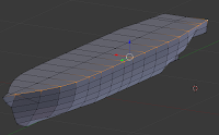
The last posting (Part 1) I wrote about creating a solid model from a 3 view that had relatively detailed outlines of loft lines on a ship's hull. Again, since the purpose of the example is to show how I did it, the model is not exactly what I would call particularly accurate. If I was to work on this for a finished version I would probably work it into a few subsections with a higher polygon count for each. Still, this should be good for now. As a reminder, this is done specifically with a somewhat deprecated version of Blender, but it should probably apply with quite a few different 3d modeling software packages. Also, this is done with an eye for a card model, but it should work fairly well with paper or plastic card scratch building.So you got the shell of the thing
We prepared the hull in the previous posting, so how would one generate the bulkheads to provide the structure for the model. It's at this point that I would start making separate files. Why? Well, this part will be somewhat destructive. This may be particular to my software set up. I've been using Blender for some time, but I'm not a Blender guru (particularly since they keep changing detail bits, which is why I haven't upgraded yet). I'm using a paper model script that allows one to take a 3d model and cut it up and "unfold" until the pieces are flat, like flattening a box for recycling. The ability to generate this easily is limited by the complexity of the model.If you read some previous postings I have made on using this script, you will read about some of the problems. Sometimes complicated internal corners, such as the ones created by bulkhead spaces, can create problems. This doesn't mean it happens all the time. Sometimes it works just fine with everything in one file of objects, but other times...well it's not so good. As a result I often have a structural file for bulkheads and such and a hull file. The important thing is that if you do this, the common points must match, otherwise trouble will ensue. I sometimes insure this by importing the hull file into a structural file as an external object so I can still see it. That is somewhat advanced and I won't go into it as it involves more complicated object relationships (Yes, true Blender people will gripe that this is a bit of a bearskins and stone approach, but it works for this purpose).
So, at this stage I'll save the hull, and then save the file as "hullStructure" to start working on the internals.
Carving out the Structure
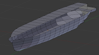
The process is similar to what went before with the hull creation. Before we created a large rectangular block to carve our shape out. In this case we want to outline the interior shapes to the existing solid. First I'm going to start the outline of the top deck. This will follow the second line from the top. Since the model is symmetrical, I'm not going to worry about generating internal spaces for the whole ship, but rather just the port side. So for starters, I selected all the vertices along the port edge of the hull.

These I deleted to make the next steps clearer.

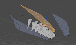
I followed this up by starting a longitudinal bulkhead along the centerline, starting at the front.

And that's basically it. At this point you can use the paper model export function in Blender to have it crank out the shapes which should come out as one piece. You may need to put seams on the long pieces (a blender operation since it is also used for defining texture skins for the model) to force breaks since depending on the scale you finally export the file (a setting on the export paper model script) they would probably not fit on a single letter or A4 sheet.
Hope this posting helps with anyone trying to create structures for their models using 3d software.


2 comments:
Please see and comment about Alexander Weygers he was the 1st with the flying saucer. 1944 us patent. invented in the 20s www.discopter.com
All the disk shaped crafts come from AGW and his vision.
Randall
rh@aejv.com
Please see and comment about Alexander Weygers he was the 1st with the flying saucer. 1944 us patent. invented in the 20s www.discopter.com
All the disk shaped crafts come from AGW and his vision.
Randall
rh@aejv.com
Post a Comment